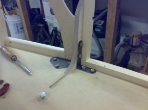
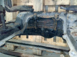
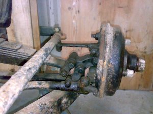
…..and work upwards. The floor is 12mm ply. The cheek on the driver’s side was later removed and a blister put on the side to accommodate the accelerator. The cheek made the body too complicated – it would have worked in aluminium but not wood.
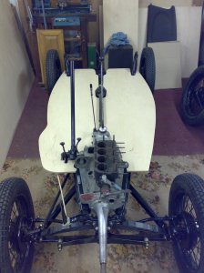
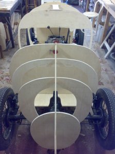
The main bulkheads are attached…
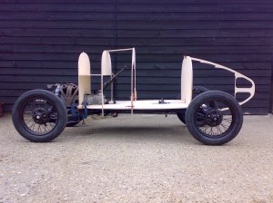
… and the shape begins to emerge.
The cockpit side rails are added. This is where I went completely wrong and had to do some major surgery a bit later on. Basically, I got the cockpit side height wrong.

Then, to brighten things up a bit, I did the aluminium for the dashboard. The engine turning was done by sacrificing an old pillar drill and sticking some Scotchbright on a flat tool. A pegged board kept the swirls in line. Do a rectangular panel and cut the shape out afterwards – an easy trick to miss if you’re over enthusiastic (how do I know this?) The sacrificial pillar drill also came in handy for scarfing the body panels but more of that later.

A steering wheel is also handy… The metal was laser cut; plywood applied to both sides of the rim and shaped with a spoke shave. Added later was the binding. It took 17 metres of cod line – more than I thought it would.

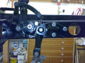
At this point some of the impossible-to-get-at-later stuff has to be done. This is the accelerator pedal bracket and lever.

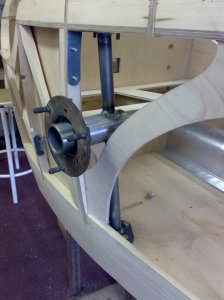
And this is the steering column into which I introduced a universal joint from a Suzuki jeep to get the right angle on the wheel.

The panel electrics are also worth doing whilst you don’t have to lie upside down in the cockpit and have pairs of pliers and screwdrivers falling into your face.

Stringers are positioned and the bulkheads notched.

The fuel tank is positioned before the stringers are finalised….

….like so.

Then the body came off the jig and was wheeled out for a photograph.

It was at this point I realised where I’d gone wrong.
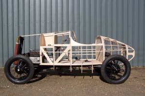
Aaaargh! It looks awful. Quick, wheel it back into the workshop and cover it in cardboard…

…. to get the lines right.

Then get the plywood on…

… so it looks as though it was always meant to be.

That’s the first one done, just the other side to do:
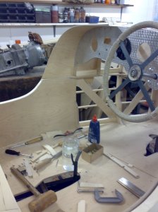
It’s a good game played slowly.
